What is a Stop and Waste Valve and Why It Matters
Introduction
The stop valve opens and closes the fluid by rotating the valve stem and is usually used in situations where precise flow control is required. In some irrigation systems, farmers may need to adjust the amount of water according to the needs of crops. The stop valve can meet this requirement and make the water flow more stable and controllable.
The drain valve is a key component in the pipeline system. It can remove mud, impurities, etc. in the pipeline in time to ensure the cleanliness of water supply and smooth drainage.
What is a Stop and Waste Valve?
Definition and Basic Function
As a manual or electric valve, the stop valve is widely used to cut off the liquid supply in the pipeline. In the petrochemical industry, the stop valve is often used to control the delivery of raw materials and products to ensure that the flow of fluids can be accurately cut off when needed. The stop valve is generally not required to be fully opened, because the main function of the stop valve is to cut off the fluid or adjust the flow. It can adjust the opening degree according to actual needs to control the flow of the fluid.
The blowdown valve is mainly used to control the discharge of fluids, especially sewage and other pollutants. It controls the relative position between the valve core and the valve seat to open, close and adjust the flow of fluids to meet the control requirements of fluid discharge. The blowdown valve can ensure the smooth operation of the system, prevent pipeline blockage, protect equipment and facilities, and extend the life of equipment.
Design and Components
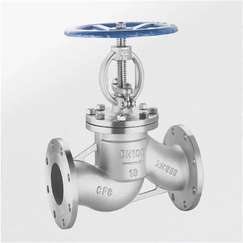
Globe valve:
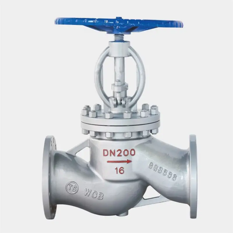
Valve body: The main part of the globe valve, usually made of cast iron, ductile iron, cast steel or stainless steel. A flow channel is provided inside the valve body for the passage of fluid.
Valve flap: The key component of the globe valve, used to control the flow of fluid. The valve flap usually adopts a double-plane hard seal or soft seal structure, made of metal (such as cast iron, copper, aluminum, stainless steel, etc.), which can effectively prevent fluid leakage.
Valve stem: The component that connects the valve flap to the actuator such as a handwheel or motor. By rotating the valve stem, the valve flap is driven to open or close.
Seal: Including sealing gaskets, packing, etc., used for sealing between components such as valve body, valve flap and valve stem, usually made of rubber, polytetrafluoroethylene and other materials.
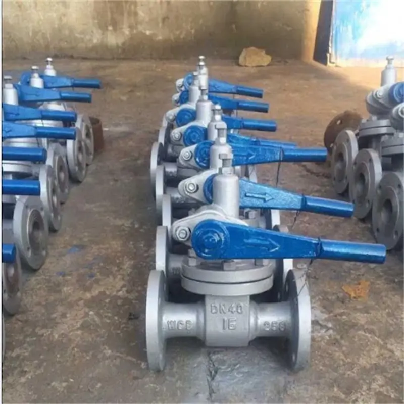
The sewage valve is usually composed of valve body, valve cover, valve disc, sealing ring and other parts. Among them, the valve body is the main part of the sewage valve, usually made of cast iron or stainless steel; the valve cover is tightly connected to the valve body to protect the internal structure from the influence of the external environment; the valve disc plays the role of controlling the water flow, and is opened or closed by rotation or lifting; and the sealing ring ensures the sealing performance of the sewage valve to prevent leakage.
1. The valve body and the valve cover are connected by clamping, which has a compact structure, easy disassembly and installation, and the branch pipe is welded.
2. The pressure self-tightening sealing structure is adopted, and the sealing ring is made of molded asbestos packing. The higher the medium pressure, the better the sealing.
3. The medium flows into the branch pipe and discharges downward.
4. The valve disc is a piston structure and is boronized. Corrosion-resistant and erosion-resistant. Long service life.
How Does a Stop and Waste Valve Work?
The working principle of the stop valve is to control the flow of fluid by the movement of the valve disc on the valve seat. The valve disc moves linearly along the center line of the valve seat, changing the distance between the valve disc and the valve seat, thereby changing the cross-sectional area of the flow channel to control and cut off the flow. The stop valve is suitable for a variety of occasions, including controlling air, water, steam, various corrosive media, mud, oil, liquid metal and radioactive media.
The working principle of the sewage valve is based on the opening and closing of the valve. When sewage or other fluids need to be discharged, the valve core is separated from the valve seat by operating the valve (such as a handwheel, handle or electric actuator, etc.), and the fluid can flow out through the valve. When the discharge is completed, the valve is operated again to make the valve core fit tightly with the valve seat to help the fluid from continuing to flow out. The sealing performance of the sewage valve is good, which can insure that there’s no leakage in the unrestricted state.
Applications and Usage Scenarios
Application scenarios of stop valves
Oil painting and gas assiduity: Stop valves are used to control oil painting well-conditioned affair, exigency shut- off or oil painting inflow regulation in long- distance oil painting channels, and fluid inflow direction and inflow control at different refining stages during the refining process.
Chemical processing assiduity: In the chemical assiduity, stop valves are used to control the inflow of raw accoutrements into the reactor, the inflow of different factors in the product separation and sanctification process, and are used in confluence with safety valves to help overpressure.
Power generation assiduity: In energy product installations similar as power shops and petrochemicals, stop valves are used to control the inflow of liquids or feasts to insure the safety and effectiveness of energy product and transportation processes.
Water and wastewater treatment: In the megacity’s valve water force system, stop valves are used to control the flux and exodus of water, maintain water force pressure and inflow, and shut off the water force when water pipes need to be maintained or exigency repairs are performed.
Medicinals and biotechnology:In these diligence, stop valves are used to precisely control chemical responses and help dangerous gas leaks.
Construction field: Stop valves are extensively used in structure water force and drainage systems to control the switching and stopping of water inflow, as well as water source control in fire protection systems.
Application scenarios of drain valves
External water force and drainage system: In civic water shops and sewage treatment shops, drain valves play a vital part. It can timely remove deposition, contaminations, etc. in the pipes, insure the cleanliness of water force and smooth drainage, and is the” strong backing” for the normal operation of civic water systems.
Artificial product field: In chemical, sword, papermaking and other artificial enterprises, a large quantum of wastewater and waste residue will be generated during the product process. Drain valves can safely and efficiently discharge these wastes, help pipe blockage and outfit damage, and insure the durability and stability of artificial product.
Building facilities: In the water force and drainage system of high-rise structures, drain valves are responsible for discharging condensed water, sewage, etc. in the pipes. It’s a”caring adjunct” for the normal operation of erecting installations.
Installation and Replacement
Choosing the Right valve
First, understanding the nature of the fluid being handled is pivotal to choosing the right valve.
Determining the flux and pressure range of the fluid is essential to choosing the right valve type.
Being familiar with different types of valves is pivotal to choosing the right valve. Each valve type has different working principles and applicable scripts.
The operating conditions of the valve are also an important factor in choosing the right valve. For illustration, manual operation or automated operation requires consideration of the control system of the valve.
Ultimately, consider the terrain in which the valve will be installed. Factors in the installation terrain include space limitations, temperature, pressure, vibration, and media characteristics. Make sure the named valve can adapt and be suitable for the conditions of the installation terrain.
Step- by- Step Installation
The disassembly and assembly process of the stop valve is as follows:
1. Close the pipes related to the stop valve in the system to insure that the liquid and gas in the system don’t flow.
2. Remove the nuts of the stop valve or the bolts on the flange to separate the stop valve from the pipe.
3. Check whether there are foreign objects in the stop valve.However, remove the foreign objects to avoid affecting the normal operation of the stop valve, If necessary.
4. Gently tap the stop valve with a rubber hammer to make the valve core move sluggishly, and also loosen the valve stem nut with a wrench.
5. Remove the valve cover, remove the valve core and valve seat, and check for damage or wear.
6. still, replace it with suitable tools and acclimate the sealing degree of the stop valve, If the valve core or valve seat needs to be replaced.
7. When assembling the stop valve, it should be done in the rear order of disassembly, and insure that the valve stem nut and valve core are tensed.
8. After installing the stop valve, open the pipes related to the stop valve in the system to check whether the stop valve is working properly.However, it should be acclimated and handled in time, If there’s water leakage or air leakage.
Installation instructions for drain valve
1. Themulti-way drain valve must be installed vertically on the vertical pipe.
2. The valve can be installed only after the pipe is gutted.
3. Turn the handwheel valve stem counterclockwise to drive the valve core to gradationally move overhead, the sealing face is disentangled, and the companion seat on the valve core gradationally moves out of the inner hole of the valve seat to form a narrow gap. The medium enters the inside of the valve seat through the symmetrical throttle hole on the valve seat. A small quantum of medium can flow out through the narrow gap, gradationally reducing the system pressure.
4. Continue to turn the handwheel counterclockwise, the valve core moves overhead, the throttle hole on the companion seat moves out of the inner depression of the valve seat, and further medium is discharged easily after strangling through the companion seat and the valve sleeve.
5. Continue to turn the handwheel counterclockwise, the valve core moves overhead to the completely open position. At this time, the medium pressure is greatly reduced, and a large quantum of contaminations can be directly discharged from the throttle hole of the valve sleeve, and a whirlpool is formed at the reversed sealing seat, which continuously cleans the sealing face to help contaminations from clinging to the sealing face.
6. Turn the valve clockwise, the valve stem drives the valve core to move down, at this time, the sewage discharge has ended, the system pressure is low, the strangling hole area on the valve sleeve gradationally decreases, the companion sleeve approaches the valve seat, and changes the inflow direction of the medium. After strangling, the medium passes through the valve core and the valve as a sealing face at a certain speed, and gradationally strengthens the cleaning of the sealing face.
7. Continue to turn the handwheel, the companion seat on the valve core enters the inner hole of the valve seat, forming a narrow tear throttling. Since the sewage discharge is close to the end, there are smaller contaminations in the medium. The narrow gap between the companion sleeve and the valve seat prevents the remaining bitsy contaminations from flowing into the sealing face. The medium flows out snappily through the narrow gap, completely drawing the sealing face, and icing zero leakage when the sealing brace connections.
8. Continue to turn the handwheel, the valve core and the sealing seat contact. Achieve sealing.
Conclusion
As a generally used shut- off valve, the stop valve has the advantages of good adaptation performance, simple structure, accessible manufacturing and conservation, and low price, but it also has disadvantages similar as fairly poor sealing performance and large fluid resistance. In practical operations, the type and specification of the stop valve should be nicely named according to the specific working conditions and use conditions to give full play to its advantages and insure the safe and stable operation of the channel system.
The drain valve is extensively used because of its simple structure, good sealing, small size, light weight, low material consumption, small installation size, especially small driving necklace, easy operation, and easy to achieve fast opening and ending.
In practical operations, the applicable valve should be named according to factual requirements, and it should be used and maintained in strict agreement with the operating procedures to insure its normal operation and extend its service life. Consult professionals for installation and conservation when necessary.