Depending on different purposes, functions and application sites, it can evolve into remote control float valves, pressure reducing valves, slow-closing check valves, flow controllers, pressure relief valves, hydraulic electric control valves, emergency shut-off valves, etc. As the use of hydraulic control valves is increasingly affirmed by more and more users, its user base is also constantly expanding. For new users, it is very necessary to understand the models and classifications of hydraulic control valves.
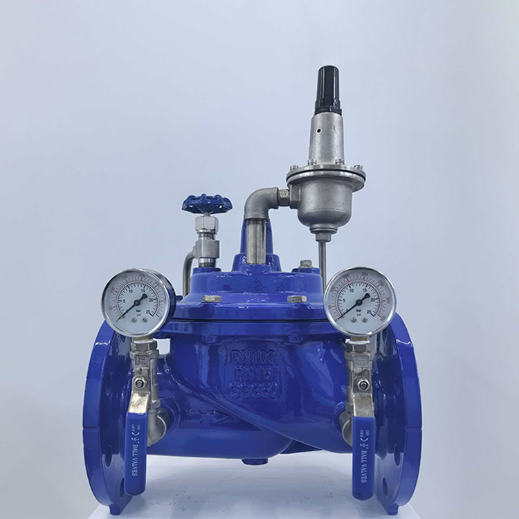
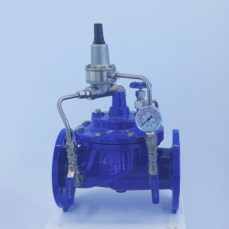
Hydraulic Control Valve Models
Model: 100X—10/16 (Remote Control Float Valve)
Model: 200X—10/16 (Pressure Reducing Valve)
Model: 300X—10/16 (Slow-Closing Check Valve)
Model: 400X—10/16 (Flow Control Valve)
Model: 500X—10/16 (Pressure Relief Valve)
Model: 600X—10/16 (Hydraulic Electric Control Valve)
Model: 700X—10/16 (Pump Control Valve)
Model: 800X—10/16 (Differential Bypass Control Valve)
Model: 900X—10/16 (Emergency Shut-Off Valve)
Model: JD745X—10/16 (Multi-Function Pump Control)
Model: F745X—10/16 (Remote Control Float Valve)
Installation methods of hydraulic control valves
When installed horizontally, the valve cover should face upwards. Drainage facilities should be provided after the pressure reducing valve in the fire water supply system. Hydraulic control valves are preferably installed horizontally, and when installed horizontally, the valve cover should face upwards. Drainage facilities should be provided after the pressure reducing valve in the fire water supply system. When pressure reduction is required in the automatic sprinkler fire extinguishing system, the pressure reducing valve should be set before the alarm valve (in the direction of water flow). For a pressure reducing valve set in conjunction with a single alarm valve, a spare pressure reducing valve is not required; for a pressure reducing valve set in conjunction with multiple alarm valves, a spare pressure reducing valve should be provided. For pressure reducing valves used in hot water supply projects, hot water type pressure reducing valves should be adopted. For hot water supply projects using the main pipe circulation method (semi-circulation method), the requirements for setting pressure reducing valves should be the same as those for cold water projects; for hot water supply projects using the riser circulation method (full circulation method), the setting of pressure reducing valves should prevent the disruption of hot water circulation, and the pressure at the convergence point of the return pipes in each zone should be balanced.
1. Generally, valves do not undergo strength tests. However, the valve body and cover after repair or those with corrosion damage should be subjected to strength tests. The set pressure, reseating pressure and other tests should comply with the manufacturer’s instructions and relevant regulations.
2. Before installation, valves should undergo strength and tightness tests. For low-pressure valves, 20% should be spot-checked, and if any are found to be substandard, 100% inspection should be carried out. Medium and high-pressure valves should be 100% inspected.
3. During the test, the valve should be installed in a position that is easy to inspect.
4. For valves with welded connections, if blind plate pressure testing is not feasible, conical seals or O-ring seals can be used for pressure testing.
5. During hydraulic testing, air in the valve should be expelled as much as possible.
6. The test pressure should be increased gradually and not suddenly or sharply.
7. The duration of strength and tightness tests for water control valves is generally 2 to 3 minutes. For important and special valves, it should be 5 minutes. The test time for small-diameter valves can be shorter, and for large-diameter valves, it can be longer. If there are any doubts during the test, the test time can be extended. During the strength test, no sweating or leakage should occur in the valve body and cover. For general valves, only one tightness test is required, while for important valves such as high-pressure valves, two tests are needed. During the test, for low-pressure, large-diameter, unimportant valves and those with specified allowable leakage, a small amount of leakage is permitted. Due to the different requirements for general valves, power station valves, marine valves, and other types of valves, the leakage requirements should be in accordance with relevant regulations.